When I ask to all my friends, my clients and my customers, are you have been saved energy from lighting system? All of them answered the result of saving from lamps or lighting system was not significant. Why? Because lamps just a little loads compare than others loads (motors, fans, pumps, etc). Yes, that's true. But otherwise, it's FALSE!!!
Why? Let's see the calculation example below after you read where are the energy saving placed.
In Lighting Systems, there are many way's to save the energies if we know and how to do that. I'll try to explain it in details.
Where are the saving placed?
1. Lighting Control
Timer Switches to turn off lights after a fixed period has passed
Occupancy sensor / movement detectors to turn off lights when no movement has been detected for a certain period
Photoelectric cells / daylight harvesting sensor to control lights near windows. When bright exterior light is available, lamps are turned off or dimmed
Programmable timers to switch lights on and off at predetermined times
Dimmable light to maintain a low level of illumination at off-peak periods
Voltage regulators to optimize the power consumed. Ballast perform this function on fluorescent lighting. Voltage regulators are also available for other lighting types such as high pressure sodium lamps.
2. Types of Lamps
Nowadays, there are a lot of types of lamps. But, we not realize that each of lamps have different characteristic and specification. For the example, the old fluorescent lamp, with T12, usually have rated power up to 40W. Today, with same intensity output of light, you can use T8 with rated power up to 36W. The conclusion is you must know about the characteristic and the specification of lamp that will be used.
3. Reflectors
Around 70% of fluorescent tube's light is directed sideways and upwards to the light fittings surfaces.
High efficiency reflector has a spectral efficiency of over 90%. This means two lamps may be replaced by a single lamps. In this way it's possible to reduce energy costs attributed to lighting by 50% or more.
4. Changing Conventional Ballast (Electromagnetic) With Electronic Ballast
Conventional Ballast have power factor (cos phi) up to 0.45. Electronic Ballast have power factor (cos phi) up to 0.95. What are the differences? See the calculation in end of this page.
5. Don't want to change Conventional Ballast (Economics reasons), Use Special Capacitor For Lamps
If you don't want to change Conventional Ballast because you have economic reasons (usually for home application), I have the alternatives. Use Special Capacitor for lamps. This capacitor had special schematic wiring diagram, so why you must use Special Capacitor for lamps.
Conventional Ballast without special capacitor have power factor (cos phi) up to 0.45. Conventional Ballast with special capacitor have power factor (cos phi) up to 0.95. What are the differences? See the calculation in end of this page.
Near from the end, The Real Calculation...
When I go with my friend to one of his customer, I just ask for their existing lighting system. They says that using all systems as similar as my design system before I explain my design to them. But they have some systems that still not applicable yet. They said that after used the lighting system, they can save the electrical bills up to 50% / months. I'm aghast with their statement. It's same with my calculation that shown below.
For this calculation, electricity rate was from my region / my country electricity goverment factory. The calculation was only in one point that include two lamps in one housing / fitting. Power of each lamp was 4o Watt, works in 220VAC 50Hz. And applicable for industrial and home applicances.
USING CONVENTIONAL BALLAST NOR SPECIAL CAPACITOR AND T12 40W LAMP (pf = 0.45)
I = (2 x 40W) : (220 VAC x 0.45) = 0.808 A P = 0.808 x 220VAC = 177.76 Watt Electricity used per month (1 kWh = Rp. 480.-) 12 hours / day x 30 days x 177.76 Watt = 63,993.6 Watt.Hours = 63.994 kWh Electricity bill per month (exclude basic load type value bill): Rp. 480.- x 63.994 kWh = Rp. 30,716.93
USING ELECTRONIC BALLAST OR SPECIAL CAPACITOR AND T8 36W LAMP(pf = 0.95)
I = (2 x 36W) : (220 VAC x 0.95) = 0.344 A P = 0.344 x 220VAC = 75.68 Watt Electricity used per month (1 kWh = Rp. 480.-) 12 hours / day x 30 days x 84.26 Watt = 27,244.8 Watt.Hours = 27.245 kWh Electricity bill per month (exclude basic load type value bill): Rp. 480.- x 30.334 kWh = Rp. 13,077.6
TOTAL SAVING PER MONTH Rp. 30,716.93 - Rp. 13,077.6 = Rp. 17,639.33
The sun has produced energy for billions of years. Solar energy is the sun’s rays (solar radiation) that reach the earth.
Solar energy can be converted into other forms of energy, such as heat and electricity. In the 1830s, the British astronomer John Herschel used a solar thermal collector box (a device that absorbs sunlight to collect heat) to cook food during an expedition to Africa. Today, people use the sun's energy for lots of things.
Being an engineer, this got me thinking, so I did some research and found a number of useful resources. The most inspiring book was ‘Cooking with the Sun: How to Build and Use Solar Cookers’ by Beth and Dan Halacy. So, I decided to make a Solar Stove in June 2007, with this website as reference.
Otherwise, in my country, Indonesia, Dr. Muhammad Nurhuda, lecture from Physics Division of Brawijaya University had develop a Solar Stove too, but its different with mine. (Source: Kompas, 13 Maret 2008).
Why use a Solar Stove?
The heat energy produced by the sun is immense. In equatorial regions the solar radiation can exceed 1000 Watts/m2. That is equivalent to half the power of an electric kettle whenever there is good sunlight. It only takes 10 – 15 minutes to boil water on a solar stove. And it’s free, as long as you have clear blue skies! If not, you can boil it in 30 minutes. The material costs are about $10 per stove which with some sponsorship is feasible to raise, and they are fun to make.
Firewood, Kerosene and Health issues
The ‘Manual for solar box cookers’ published by Technology for Life, Finland quotes: -
"About 2000 million people, over one-third of the population of the world, are daily dependent on firewood as the source of their cooking and heating energy. They live in the tropics, in the most favourable areas for the use of solar energy. Every year the cutting of firewood results in the loss of 20,000 - 25,000 km2 of tropical forests (UNEP).
The use of solar cookers also brings with in important health benefits. Diseases spread through contaminated water cause 80% of the illnesses in the world (WHO). Heating water to the pasteurization temperature of about 60 0C destroys disease organisms. This temperature is easily achieved with solar cookers. Acute respiratory infections (ARI) are the cause of death for millions of children in the world each year. The large majority of these casualties occur in the developing countries as a result of polluted indoor air due to cooking over open fires in houses without chimneys or ventilation. This problem could be greatly reduced by using solar cookers, which are, of course, completely smokeless."
In Indonesia, kerosene was become primary needs for the source of cooking. Nowadays, the kerosene was rare and the government change it with natural gas. But, it's not renewable energy and it's still to expensive than buy kerosene stove and kerosene's.
How does a solar stove work
There are two basic methods of collecting enough heat from the sun to cook. These are commonly described as the ‘Solar Box Cooker’ and the ‘Solar Stove’.
Solar Box Cooker
The basic principle is to collect the heat by letting the sun light pass through a clear glass plate into a well-insulated enclosure. The light ‘trapped’ in the box and turns into heat when it is absorbed by the black cooking pot. The secret of a good Solar Box Cooker is to have good insulation with no air gaps and a good lid reflector to get the most light into the box. Cooking times are not that quick, but temperatures of 150 0C are possible.
Technology for Life, Finland has documented the Solar Box Cooker with great accuracy. For more information, click this link.
Solar Stove
The Solar Stove uses a parabolic reflector to focus the sunlight to one point. This produces the effect of a massive magnifying glass. With an accurate reflector it is possible to get ‘times 100’ magnification. The reflector is aligned to point at the sun, and then the black cooking pot is placed on a grill at the focal point. Being black the pot absorbs most of the sunlight and creates sufficient heat for cooking.
Precautions for use of solar stoves
Do not look at the reflection of the sun at any time. Once the stove is in alignment with the sun, and the pot is at the focal point, then there should be no light scatter. If there is ‘stray’ light then the stove may need adjustment such that all the reflected light hits the pot (this will improve your cooking as well).
When adjusting the angle of the grill use thick gloves as the grill can get very hot.
Materials required
The most important material in the stove is the reflective aluminum sheet. This I was fortunate to obtain courtesy of my ex. employer. The size of sheet was limited to 400 mm x 620mm as this fitted nicely in my suitcase. The aluminium is available from a number of suppliers, but the reflective qualities are important. I used 0.3 mm AnocoilÓ grade 710.33 which is 86% reflective and almost mirror quality.
The main enclosure is cut from 4 mm thick ‘Triple A’ plywood. An 8ft x 4ft sheet will make 21 stoves and only costs $5. A few other bits of wood are required to make the framework within the stove (sizes detailed below).
As the focal point gets very hot it is necessary to make the grill and grill support from metal. I used mild steel and painted it silver, but any metal will do.
Useful tools include: Drill, jigsaw, hacksaw, vice, wood saw, sharp ‘Stanley’ knife, tape measure, square, metal file and hammer.
Optional tools include: Grinder and welder.
Building the solar stove.
We split the work up into three sections. Manuel Reynaga was in charge of the metalwork, David Coe organized the lads (and one girl) in cutting the cardboard ribs, and I was in charge of the woodwork. We rotated the work, so they all had a go at each discipline. I was amazed how keen they all were to get things done. Once they saw the water boiling on our prototype they all wanted one!
1. Woodwork
I made up some templates for the sides and base, and cut them out using a 'jigsaw' power tool.The edges were filed flat. We then cut the frame parts to length and nailed the whole box together around the frame. See drawing WOOD for dimensions. Once the enclosure was assembled we made up the wooden SUPPORT at the base. This had the main purpose of holding the 16mm bar and grill in place. The support was nailed to the underside of the wooden box. To help align the stove with the sun we made a sundial by fixing a nail through the support at the edge parallel to the 16mm bar. By adjusting the stove to eliminate any 'shadow' of the nail it is easy to find the sun's location. See drawing GA for details.
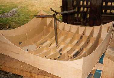
2. Cardboard
Finding enough cardboard for 10 stoves was surprisingly difficult, but the 'Lord provided' just enough. The reflector profile is spherical with a radius of 0.7 m (equal to the square size of the enclosure). This gives an almost parabolic shape with a focal point at 0.35 m from the reflector. We used the 'wine box' principle of interlocking cardboard to create the required shape for the reflector to fit into. Ideally the box should be square (0.7 m x 0.7 m) but as our aluminium was not big enough we had to make it only 0.56 m wide by 0.7 m long. I designed the rib shapes on the computer, but it only takes a bit of Pythagoras to work out each radius. See drawing RIBS and RIBSX for details. Each rib is 0.07 m apart and 11 ribs are required to make the shape (including the two wooden ends). Each rib has a different radius depending on its location. I have designed a GENERIC profile that can be scaled up to any size of stove.
3. Metalwork
The hacksaw, drill and vice came in very handy. The three main items are the BAR, GRILL and PIN. The bar pushes into the wooden base and is located in place with the pin. The grill is fixed to the bar with an M5 x 20 screw with a wing nut and spring washer. This allows the grill to be secure but also adjustable as the sun changes height. The bar and grill were painted silver to reflect more light. See drawing GA for details.
4. Reflector
Once all the parts have been made they can be assembled into the box. The cardboard ribs should just drop in and sit flush with the base. If there are gaps under some of the ribs then it is probably because the slots in the ribs are not deep enough. Fitting the reflector is the final thing to do. We marked the reflector on 15 degree angles and then cut through with a very sharp knife leaving an area in the middle uncut. Take care of your fingers, we only had one accident! See REFLECTOR drawing for details. We then placed the reflector on top of the box and ribs and cut the edges to length. The reflector was then taped down around the edges, which produced an accurate focal point. We used shiny aluminium foil to tape the reflector in place. We found that the best method was to tape alternate edges first. This enabled us to push the other segments firmly on top of the first segments. It is worth spending time in getting each segment just right as this affects the focusing.
Maintenance and caring for your solar stove
When not in use, keep the stove in the dry. To store the unit in winter, remove the grill and grill support and turn upside down.
A dirty reflector will slow down the cooking times. Clean the reflector with a dry cloth or 'alcohol' if available.
Cooking tips Black pots work a lot better than silver pots. The pot needs to absorb as much light as possible and silver tends to reflect the light. Dull or 'matt' finishes absorb more light than 'shiny' surfaces.
Pots with close fitting lids keep the heat in and help the cooking process. Placing the stove in a sheltered area stops the wind from cooling the outside of the pot.

 High efficiency reflector has a spectral efficiency of over 90%. This means two lamps may be replaced by a single lamps. In this way it's possible to reduce energy costs attributed to lighting by 50% or more.


 The edges were filed flat. We then cut the frame parts to length and nailed the whole box together around the frame. See drawing
 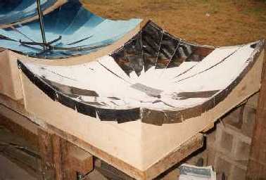 The cardboard ribs should just drop in and sit flush with the base. If there are gaps under some of the ribs then it is probably because the slots in the ribs are not deep enough. Fitting the reflector is the final thing to do. We marked the reflector on 15 degree angles and then cut through with a very sharp knife leaving an area in the middle uncut. Take care of your fingers, we only had one accident! See


